Due to the lack of remaining room under the bonnet, I had recently decided to only carry 6 batteries up front. (despite designing the front rack to hold 7 blocks.
In the 7th battery position I will be making and mounting the high voltage control box and the controller.
This is what i've been working on since back from holidays ... ...
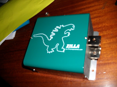
Before I start going on about the high voltage you can see in the image below i have mounted the Zilla control panel (green) on the far left of this upper battery rack. Also mounted a 150mm 12V fan below the rack on the right, to cool the motor if required. The vacuum reservoir for the power assist brakes is mounted below on the left

OK ... where do we start ...
The yellow section is the bottom level of the high voltage control box ... This is where the power from the batteries will come straight into 2x Airpax Circuit Breakers ... These breakers are rated at 160V and 800A trip each ... I will probably only activate one to start with ... but I like to over engineer everything.

From the breakers the power runs through the 1000A shunt for one of my Amp Meters ... then straight up to the upper level ...
Instead of having thick cables run everywhere, I made my own copper bus bars by bashing out 25mm copper tubing. Most connections are using double bus bars so as to keep the cross section of copper the same as the cables in the circuit.

In the top level of the Power box I have:
1x contactor for saftey cutoff (top middle) which feeds the other 3
1x contactor for activation of the controller (top left)
and the other 2 contactors are for the high voltage going to the DC-DC converter and the heater core.
There is also a small fuse block for the DC-DC and Heater.
You can also see mounted behind (to the right) of the power box is a large heatsink which the controller and the heater core relay will be mounted to.
The Zilla gets most of its cooling via liquid cooling fittings on the rear of the controller. But for lower current draws, a heatsink should be sufficient. The heatsink i'm using is a bit hard to see from these pictures but it has over 10cm long fins underneath.
I will also be looking at using the liquid cooling ... I have purchased a pump and would like to use the cabin heater core that I removed earlier as a cooling radiator.
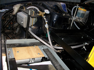
With that battery rack mounted back in the car, (hopefully for the last time) I attached the remaining components of the KTA Vacuum Kit I purchased ...
The kit I purchased cost AU$617 ... and included everything from the vaccum pump an reservoir to the hoses, brass fittings and ring clamps.
You can assemble you own kit by making your own reservoir out of pvc, getting your own fittings and sourcing your own pump, but for a couple of hundred dollars extra it was one less thing I wanted to worry about.
The pump is mounted under the grey rack, Reservoir just visible under the black rack, you can see the aluminium check valve along the hose just before the pressure gauge and large grey square vacuum switch.
Upon installation of the kit I have noticed it has trouble reaching the correct vacuum and drops rather quickly ... Crimping the hose up near the brake booster I have noticed there are no such pressure problems. So the kit is working correctly and there must be some sort of leak inside the brake booster ... I'll have to remove the booster and see if I can get it reconditioned.