Thursday, January 28, 2010

Control Box and Vacuum Pump

Due to the lack of remaining room under the bonnet, I had recently decided to only carry 6 batteries up front. (despite designing the front rack to hold 7 blocks.
In the 7th battery position I will be making and mounting the high voltage control box and the controller.

This is what i've been working on since back from holidays ... ...

Before I start going on about the high voltage you can see in the image below i have mounted the Zilla control panel (green) on the far left of this upper battery rack. Also mounted a 150mm 12V fan below the rack on the right, to cool the motor if required. The vacuum reservoir for the power assist brakes is mounted below on the left


OK ... where do we start ...

The yellow section is the bottom level of the high voltage control box ... This is where the power from the batteries will come straight into 2x Airpax Circuit Breakers ... These breakers are rated at 160V and 800A trip each ... I will probably only activate one to start with ... but I like to over engineer everything.


From the breakers the power runs through the 1000A shunt for one of my Amp Meters ... then straight up to the upper level ...


Instead of having thick cables run everywhere, I made my own copper bus bars by bashing out 25mm copper tubing. Most connections are using double bus bars so as to keep the cross section of copper the same as the cables in the circuit.


In the top level of the Power box I have:
1x contactor for saftey cutoff (top middle) which feeds the other 3
1x contactor for activation of the controller (top left)
and the other 2 contactors are for the high voltage going to the DC-DC converter and the heater core.
There is also a small fuse block for the DC-DC and Heater.

You can also see mounted behind (to the right) of the power box is a large heatsink which the controller and the heater core relay will be mounted to.

The Zilla gets most of its cooling via liquid cooling fittings on the rear of the controller. But for lower current draws, a heatsink should be sufficient. The heatsink i'm using is a bit hard to see from these pictures but it has over 10cm long fins underneath.
I will also be looking at using the liquid cooling ... I have purchased a pump and would like to use the cabin heater core that I removed earlier as a cooling radiator.
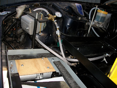


With that battery rack mounted back in the car, (hopefully for the last time) I attached the remaining components of the KTA Vacuum Kit I purchased ...
The kit I purchased cost AU$617 ... and included everything from the vaccum pump an reservoir to the hoses, brass fittings and ring clamps.
You can assemble you own kit by making your own reservoir out of pvc, getting your own fittings and sourcing your own pump, but for a couple of hundred dollars extra it was one less thing I wanted to worry about.
The pump is mounted under the grey rack, Reservoir just visible under the black rack, you can see the aluminium check valve along the hose just before the pressure gauge and large grey square vacuum switch.
Upon installation of the kit I have noticed it has trouble reaching the correct vacuum and drops rather quickly ... Crimping the hose up near the brake booster I have noticed there are no such pressure problems. So the kit is working correctly and there must be some sort of leak inside the brake booster ... I'll have to remove the booster and see if I can get it reconditioned.

Christmas Presents for Me !!!

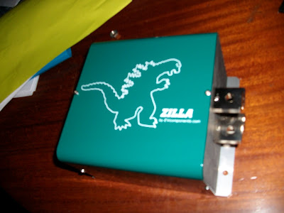
Well ... after a few months in production my 1K Zilla was finally shipped out ...

It was received into Aust Customs 08-Dec but since I was on holidays I was only able to chase it up and get it cleared mid Jan.


Here is what AU$2800 buys you. (Including all freight duty and GST)

Well you also get the Zilla control panel, cables and a manual ... but i've lost them already ... ... ...
Just kidding !!!
My project was pretty much on hold awaiting the controller, so I could verify space requirements, cable lengths etc ...
But now i'm back at it ...
I also visited the Brisbane AEVA monthly meeting held at Albion ... ... There were a few interesting topics covered ... mainly for me the next NCOP14 (code of practise for converting to electric drive) revision, is doing away with the requirement of an in cabin manual cut of the traction pack. Instead you will be able to use low voltage contactors to cut the traction pack power. Good news for me as I didn't really want to install a choke cable to my circuit breakers incase of emergency ... Now I can have a red button which cuts power to any number of contactors in my traction pack.

Thursday, December 10, 2009

DC-DC Converter installed

For now I am going to use a small car battery to power the car's 12V system ... With a DC-DC converter to recharge this battery off the main pack (kind of like an alternator).
I am going to try and mount both the battery and the DC-DC converter in the standard battery position.

The first problem I had to face was that the DC-DC converter closely resembles a computer power supply. So the last thing I wanted was for dirt or water to be sucked through the unit.
My first idea was to buy an airtight food container and mount the DC-DC converter (and a few other things) inside ... Here is the container I picked up from K-Mart ... It is slightly larger than the DC-DC converter.Then:
I mounted the DC-DC on one side leaving an airgap below
I drilled out another side of the container for air intake and made a foam filter
I installed a 12V extraction fan on the lid
I installed the 50A shunt for the low voltage ammeter
I installed 2x 12V relays with their own fuses (for the power steering pump and vacuum pump)
I installed a 40A DC circuit breaker for all the cars remaining 12V power.Basically what this unit does is the car battery 12V positive power goes in one end ... runs through the shunt ... splits in 3 (the 3 large bolts on top) for the power steering, vacuum brake booster and remainder of the car. All while keeping my DC-DC converter and relays away from any dirt under the bonnet.

Wednesday, December 2, 2009

Pot Box Installed

While i'm still awaiting delivery of my controller, another job that can be done was to mount the potentiometer and connect it to the standard throttle cable ...
Once again I have gone crazy with the welder and made a custom mount for this.I found a nice spot for this in the centre of the firewall just above the electric motor.
Since I haven't decided where the controller will be mounted as yet, having the pot box centralised should give me plenty of cable length later on.
It's a bit hard to see from these pics but at the top left of the metal mount I have added an extra piece of steel with a mounting hole for a second return spring.
I haven't sourced one yet but it is part of Australian guidelines to have a secondary return spring in case of failure.
Here are a couple of picks how the engine bay is looking at present.

Tuesday, December 1, 2009

Power Steering Pump Installed

It's been a while since my last post, but I did complete a few tasks in November.

With my front battery rack near completion, I began the task of finding mounting positions for the extra equipment needed under the bonnet.
The electric power steering pump is one of these.
I've been having so much fun with my new found welding skills that I decided to knock up a custom mount for the pump to attach it to the firewall near where the car's original 12V battery sits.

Here is a pic of the Power steering pump mounted in the car.
I had to source a custom high pressure line for $80 from the local hydraulic hose supplier ... but was able to recycle some of the 300zx old Power steering lines for the return feed.
I still don't know what car this pump was originally from ... but it looks fairly heavy duty.
I have powered the pump up to check that it works ok and to test out my relay wiring.
As the high pressure line weaves amongst my front battery rack, I haven't filled it with fluid as yet.
Once I am convinced I won't need to adjust the front battery racks any more, I'll test out the steering and my hose connections.

Monday, October 26, 2009

Engine Mounts Done

I've been spending about 30 mins each day Cutting Grinding Welding ...
The battery boxes are about half completed ...
But i'm finished with my first attempt for the motor mount.
I've mainly used 40x3mm angle iron with double 20x3mm strip for the banding.


This is the right hand side ...


And the left ...

Saturday, October 10, 2009

Welding Woes

Well after speaking with a couple of welders, I decided to give it a go myself.

I took my angle grinder to the boot and cut out the largest "non load bearing" section I could.

I purchased about $60 worth of angle iron, borrowed a $100 arc welder and went at it.

I've never touched a welder before, but i'm quite enjoying having a go.

Many of my welds look a bit messy ... but I can always get them redone once I have designed the boxes. Here is a photo of the rear battery box about half done.


I was really just practising with this rear battery rack because the most difficult job was making the new engine mounts and front battery rack.


After about a week of practise, I started working on the engine mounts.

Here is a photo of the motor in the car ... I have about 15mm play between the firewall chassis on top and the power steering rack below. You can see just above the motor, one of the two existing engine mounts I need to utilise.


As there is only one mounting bolt on the outside of the motor housing, my initial plan is to create a flat beam between the two engine mounts for the motor to rest on and then attach the beam to the mounting bolt and steel belt to stop rotation.

A weekends effort cane up with these ...

I don't know if it will be sufficient, but i will wait until i install these two before I create any more.

Friday, September 4, 2009

Motor and Gearbox are Now One

Well, it has finally arrived ... the day that my forklift motor and gearbox are adapted.

With a little more guidance from DIYELECTRICCAR.COM I wired it up to one of my 12V blocks.

I was a worried what to expect as i didn't even get a chance to test the motor before I handed it over to the engineers. But it spun to life.

The engineers took forever but did a fantastic job ... Not only did they make the coupler and adapter plate under their quote of $1500 but they also advanced the end housing, sourced a bearing that was missing and polished the rotor at no extra cost.

I supose my job was on the backburner while other work was completed ... Hey, if it saved me hundreds, I couldn't be happier.

Next is to get this sucker mounted in the car and design battery racks to go around it. So, lets start looking at welders.


Wednesday, July 22, 2009

Power Steering Pump

One of the few remaining components I need to source was an electric power steering pump ...

12V electric power steering pumps are used on later model cars like the Toyota MR2 and Holden Astra ... ... I was looking for one that had the PS fluid reservoir attached.

Sourcing one has been a task ... No luck at local wreckers, I've been outbid on plenty of MR2 PS pumps out of the US and Astra pumps from the UK are expensive to ship back to AU. I did finally get one from EBAY ... don't know what car it is from but it looks pretty heavy duty.
It will probably take about 2 weeks to arrive but i'm in no hurry since I haven't seen my motor/gearbox back from the engineers.


Speaking of which ... I went and saw the engineers about 2 weeks ago to see how it was progressing ... I also asked whether they could tackle the issue of advancing the brushes in the motor. (turning half the motor casing 13 degrees in the opposite direction of rotation) ... and they said it wouldn't be a problem.

They had made a template for the adapter plate but not much else had been done so far ... The motor was still sitting on the floor strapped to the pallet it shipped with.

I have all faith in these guys coming through for me though.

Further update ... today I gave them another call and they tell me we should be looking at end of next week ... eeexxxcellent ... ... I forgot to ask about the advancing of the case again ... ... but still eeexxxcellent ...

Thursday, June 18, 2009

Batteries, Gauges and Heater Core

Now your pretty much up to date.
It is now mid June ... and the projects i've been working on this month are:


The Battery Boxes:
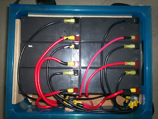
Turning 12 of these 7.5Ah 12Volt batteries

Into This

A 12V 90Ah Battery Box ...

The Idea is to have 13 of these Battery Boxes wired in series to create 156Volt

This part of the project is turning into a real chore with charging of the individual batteries, testing, endless wire cutting and crimping, modifying of the boxes, timber insert cutting ... etc...

I'm finding nearly every second of these used batterys to be ok ... so for now a couple of hundred dollars on cable and boxes is a better option than spending a few thousand for a new set of batteries.


Gauges, Switches and Wiring Harness:


Mounted on a plywood face plate, I have installed the LCD Meters and an array of illuminated switches which will control the gauges, main power, heater core, power steering pump and vacuum pump. i have also wired all this to a detachable plug and a custom wiring harness.


Heater Core:

Because the ICE no longer supplies hot water for the cabin heater, an alternate electric heat source needs to be installed.


Pictured here is the original 300zx "under dash" heater core and a timber frame i made with the same dimensions.

Thanks to kiwiev.com for the idea ... which is to use a 1600Watt ceramic heater core from a $20 fan heater.

Although used with 240V AC, these heater cores will heat to 100 degrees in seconds when connected to high voltage DC (156V in my case) ... The heater core will be not only activated by a switch on the dash but also fed from the cabin fan power. This way the heater core will only be activated with the dash switch on and the cabin fan running ... (see kiwiev.com for a better explanation)

Pictured here is my second attempt at this heater core. I still have more testing that needs to be done before I will feel safe about mounting this back under the dash.

Motor Coupler and Adapter Plate

End of May 2009 / Start of June 2009,

I spent a day driving around Brisbane chatting with various engineering companies about the fabrication of the motor/gearbox shaft coupler and adapter plate.

Many didn't know how to handle the "splined" shaft off the engine to fabricate a suitable coupler.
But I did find 2 companies before long that could help.

Winch Engineering at Rocklea & Extensive Engineering at Capalaba.
As both engineering companies quoted about $1200, I ended up taking the motor, gearbox and clutch plate into Extensive Engineering purely because they were closer to home ...
Hopefully they will have something for me by end of June.

All the Small Stuff

I also began sourcing the smaller electronic components I would require for the build

Contactor ... Tyco EV200 ... Rated to 320Volt ... Capable of breaking 2000Amp ... x3 ($300)

Circuit Breaker ... Airpax JLE-1-1-53-3-B4-250 ... Rated to 160Volt 800A Trip ... x2 ($590)
4x Panel Meters ... 500Volt, 1000Amp, 50Volt, 20Amp with shunts ... ($250) ... These will be used to monitor the 12V and 156V circuits.

2x Solid State Relays ... Rated to 250Volt 40A DC ... ($40) ... These are used to control the high voltage devices like an electric heater core.

DC-DC Converter ... Rated 144-288Volt to 12-15Volt 486Watt ... Purchased from evpower.com.au ... ($306)

12 Volt Vacuum kit for Power assisted brakes ... Purchased from KTA Services ...

Potentiometer ... Curtis PB-6 ... Purchased from KTA Services ...


Wednesday, June 17, 2009

12V Testing and the Motor

May 2009 ... Plugging a 12V power supply back into the 300ZX I started testing the 12 Volt equipment in the car to see what needed attention.

Headlights ... Worked
Indicators ... Worked
Windscreen Wipers ... Worked
Cabin Fan ... Needed to ensure all sensors were reconnected ... but finally worked

The horn still needs attention
Removing the ECU and the ECU/Engine wiring harness hasn't affected any of the 12V equipment ... That was a huge relief !!!


The Motor:

I have also decided on a motor ... ... Originally I was looking at a Netgain Warp11 Series DC motor specifically "designed" for electric vehicle use.
From the research i've done ... this was the motor to get for a performance DC conversion ...

A standard Series DC motor of this size is normally rated at about 48Volt. Whereas a performance EV conversion requires a motor to be run at 120 Volt+. A DC motor is generally capable of running at a much higher voltage than it is rated, but with such an increase in voltage causes arcing on the motor's brushes (which is a bad thing) ... These Netgain Warp motors are shipped with the brushes pre-advanced to prevent this arcing. There are many happy EVers out there using these motors, so it seemed like the way to go. But for AUD$5500 this wasn't a decision to be taken lightly.


After much thought I decided to take another track ... I sourced a similar series DC motor, from a second hand forklift recycler in the US. (I did try and find one in Australia but forklift recyclers I spoke with hadn't heard of a 10" or 11" DC Forklift motor.
This is the 11.5" 120kg Clark Series DC forklift motor. As far as the "experts" have commented ... It has potentially the same power capacity of the $5500 Netgain Warp 11 motor, at a fraction of the price. Bought for AUD$500 plus $830 delivery and best of all "no duty" was needing to be paid. I'm taking a bit of a gamble with an unproven motor, but this will save my budget $$$

Once received, the motor appeared to be in pretty good condition, with good sized brushes and a good ammount of comm bars. ... ... I haven't had a chance to power it up though (remember to only use 12V on a motor without any load) and since i'm looking at a 156Volt conversion, i'll have to look into advancing the brushes also. Better info on brush advancement can be found here http://www.hitorqueelectric.com/


The only other downside with this motor I could see was it only had one shaft, unlike the Warp11 having double shafts. One shaft needs to be connected to the gearbox and quite often you can use the second shaft at the front of the motor to power accessories like Air Conditioning or a RPM sensor. Well, this made my mind up about another variable ... I was wanting to lose the Air Con equipment to make better room for the batteries and now with no extra shaft to connect the compressor to, it was a no brainer ... ... all Air Con lines, Condensor and Radiator have also now been removed.

Further Removal of Parts

March - April 2009 i spent further removing parts off the 300ZX and selling them to clear room in the backyard.

Engine and boxes of junk ... ... Gone

Intercoolers ... Gone

Fuel Tank ... ... Gone

Fuel Lines and HICAS Steering Lines ... ... Gone

Radiators ... ... Gone

Power Steering Pump ... ... Gone

Starter Motor ... ... Gone

ECU and wiring harness ... ... Gone

Exhaust Pipes ... ... Gone

Clutch Pedal, and Master Cylinder ... ... Removed but not sold yet

Alternator ... ... Removed but probably won't sell

Skin off my knuckles ... ... Gone

Oil patches on the concrete ... ... Gone


Things I kept were:

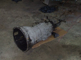
Gearbox

Tailshaft

Engine Mounts

Clutch Disc from Motor (might be needed for motor coupler)

All Air Con Equipment and Pipes(don't know if it will stay or go yet)

All Brake components
All Power steering components (except the pump)
The engine bay looks very bare now ... ... Oh, I managed to find my label maker too.
Removing of all these items would have taken the 300ZX from 1600kg to about 1200kg.
It also returned about $1000 to my budget !!!

Engine & Gearbox Removal

February 2009 was spent removing the motor and gearbox before the 300ZX was brought home.

As you might be able to tell from the photo, There is alot crammed into these cars
It's not an easy job Internal Combustion Engines (ICE) have of turning petrol into hydrocarbons, nitrogen oxide, carbon monoxide, sulfur dioxide and other hazardous air pollutants ... all while creating large amounts of heat and noise ... Oh yeah ... and powering the vehicle.

The ICE also makes a far better step stool than an electric one would anyday.

I'm glad I don't have to put any of this junk back in ... (because I forgot my label maker at home)

OK, Here's some wires ... which one do I plug the electric motor into ???

With my limited mechanical knowledge when it comes to cars ... It pays to have a qualified Nissan Mechanic as a brother-in-law ... ... (Thanks Nicko ... getting the motor out of this thing was no small task, but it was enough to get the wheels turning "so to speak")
The gearbox and tailshaft came out too ... but i'll be keeping these for later