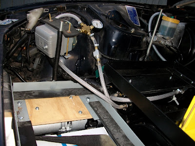
As you can see ... There isn't a whole heap of room left under the bonnet ... It only just closes at 3 levels.
The not so good news from the engineer ...
I had an engineer inspect what i've done so far ... most things he was happy with ...
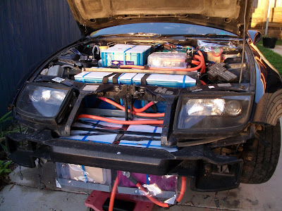
Things he didn't like were:1. The 2 battery boxes placed right in the nose ... Apparently there can't be anything in front of where the original radiator sat as it is classified as a crumple zone - My options were to put an additional 2 blocks in the boot ... but that would take the weight to about 250Kg in the rear and 220Kg up front ... I'll have to review this further when I get closer with the rear battery rack ... But I think i'll probably ditch the 2 blocks and just run on 132 Volts till I look at Lithium. For now i'm leaving the 6 (72V) up front to test.
2. Apparently i'll need more welding to tie down the front battery rack ... The engineer stated a few times it had to withstand 20x it's own weight in the upward direction (Eventhough checking the NCOP is states only 10x in the upward direction) ... Anyhow it won't be too much of an effort to add extra steel and welds to the front rack.
3. The engineer also mentioned that the engine mounts may not be sufficient ... I don't think this was something that wouldn't get passed on rather just a suggestion ... So I'm testing it the way it is for now ... I have identified a couple of stronger places to put a mount but I really need the car up on a hoist and a professional welder ... Maybe once it starts moving.
 So, here we are ... still up on stands ... 2 issues still remain before I take it for a drive.
The Brakes
I have fully installed the vacuum kit and it appears to function properly ... But the brake booster wasn't holding the vacuum and if you hit the pedal I only get 1 good stop and the vacuum drops to 5Hg (you should have 15-20Hg). Assuming the booster at fault, I removed it and sent it off for reconditioning ... Problem was the recon shop stated it was functioning properly and didn't really need the $400 service. It apparently had a very small leak but would still function properly. Back installed in the car and the same problem occurs ... pump only getting to 15Hg and only holding vacuum for 1 stop ... After much discussion on the forums my options are as follows. Increase the vacuum reservoir size and reset to 15Hg to see if that is sufficient braking capacity. Or get the reconditioning done on the booster for $400 in an effort to stop any slow leaks. I think I will try and add an extra reservoir this weekend nad see how that goes ... otherwise back off the the brake shop.
The Gauges
After blowing my HV voltmeter all over the cabin, I suspect it has also damaged my 1000A ampmeter as I am getting no signal from this ... These are only $20 meters so it is no problem to get replaced ... I contacted the seller and apparently they are on Chinese New Year till Feb-22 ...
I really need to get Amp usage information when testing the car on the road. So i'lll just have to wait till end of Feb to get my hands on replacement gauges. ... It may take me a couple of weeks to get my brake problem sorted anyhow.